Corset Module
It is identified with the following icon:
We can make a corset from a scan. In this case, before uploading the scanned form to the corset module, we must take it to viewer module, where “we will distill the form” to a circular file type. Please see this tutorial go to the Visor module.
We can also use the library to make a corset, introduce a few measurements, using photographs and an x-ray.
NOTE: in the corset library, all files that start with CORSÉ will have the built-in “history” of their tools incorporated. Those who do not start their name with CORSÉ will not carry the “historic”.

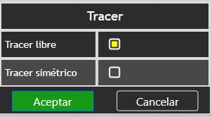
A) Palette of Pi.Cas.So. with its tools, will be opened by approximation.
B) Reference measures
- Total height: total height of the shape.
- Height: height up to the yellow line.
- Perimeter: perimeter marked on the yellow line.
C) Cursor to give more opacity to the form (for superposition of photographs)
D) Different positions of the shape positioned according to the axes.
E) View of the longitudinal section of the shape
F) Cross section of the shape, right in the yellow line, we can see it in the form and in the cross section.
G) Different cross-sectional view positions, depending on the axes.
H) Main view of the shape
I) Historical (H) and minimize (-) icons.
Cross-sectional and longitudinal measurements.
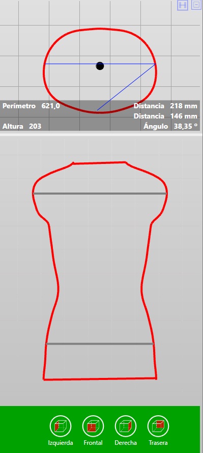
We can make linear measurements and measure their angles in the cross-section as in the longitudinal.
We click at the beginning of the measurement and holding down we will move until the end of the measurement (we will see how a blue line is drawn)
At the end of the measurement, if we press again and continue the stroke, we will be drawing another new blue line, start where the previous one ends and to finish the measurement we will do as before.
We will also see the angle of the two lines.
The strokes will remain marked as long as the mouse cursor remains in the view where we have made them. If you move the cursor from the view, the blue measurement lines disappear.
In the transverse view also we will see the height where the cut we are seeing, as well as its perimeter.
With the same logic can be done in the longitudinal view.
Position.
Shapes in the library should be properly positioned. The forms that we must position are those that we scan. Before starting to work on this module with a newly scanned form, we must first open it with the viewer module, “positioning it” and “distilling it”. Please read the display module beforehand.
However, we can see in the graph below the correct position of the model, with reference to the axes x, y, z.
Go to Position ![]()
Click on Position ![]()
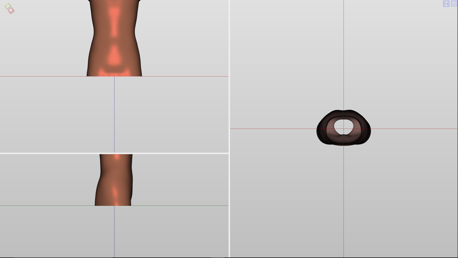
The three-axis view appears (see top graphic).
Clicking on any of the three shapes, the clicked form will assume a yellow colour.
To rotate the shape, use the mouse wheel
To make a translation of the form, use the cursor ![]() clicking on the shape the cursor will change
clicking on the shape the cursor will change ![]() dragging the shape to the desired position.
dragging the shape to the desired position.
After the change is made, you must validate it or not by clicking on ![]()
Finally, you must save the change by clicking on 
NOTE: the importance of positioning is logical, both in the superposition of photos and for the correct vision of the views, there must be a good positioning. It is important when we pass a job to the library for future use. Remember also that the shape must be on the X and Y axes (touching the axes) and the Z must be as centred as possible.
Introduce levels.
Go to Position 
Click on Levels 
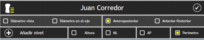
The following dialogue box will appear on the form:
– The explanation for the dialogue box is as follows:
![]() indicates the tool that we are using.
indicates the tool that we are using.
Juan Corridor: is the name of the patient.
Diameter view: diameter of the shape as we are seeing it, at the level that we mark.
Diameter shaft: diameter in the level that we mark attending to the z-axis.
Anteroposterior: total length of the anteroposterior level.
Anterior-Posterior: indicates the length before the axis and posterior to the axis.
Add level: when we add a level, we will put in the form the level and later we will click on to add level putting the name.
Height: will indicate the height at the point where we add the level.
ML: will indicate the mediolateral measure of the form where we have added the level.
AP: will indicate the anteroposterior length of the form where we have added the level.
Perimeter: it will indicate the perimeter of the form where we have added the level.
NOTE: if the dialogue box in the current view bothers us, we can change it. To do this, click in the box where the patient’s name appears, and without clicking, drag the dialogue box and position it in the desired zone.
– To add levels:
Use the cursor to mark the desired level.
A yellow line will appear. We can reposition it by pressing on it and dragging it to the desired zone.
Click on the “plus” icon to add level ![]()
The following dialogue box will appear:
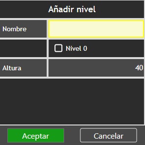
In the blank box, enter the name of the marked area.
We will mark the box Level 0 when we want the marked line to be level 0.
Height will show the height measurement on the marked line (yellow).
If everything is correct click on Accept.
In the same way, we will introduce the rest of the levels, until there is a chart like the following:
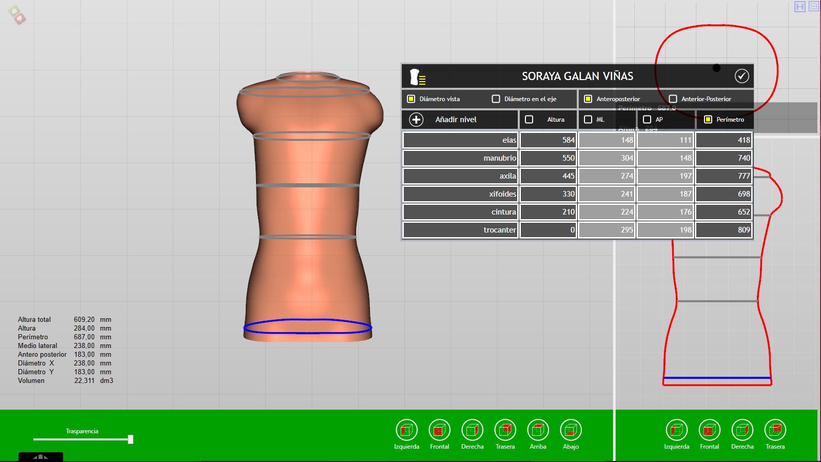
The blue perimeter will indicate “0 level” (in this example the trochanter)
In grey lines, we can see the other levels.
NOTE: we recommend first entering the desired “level 0”, adding the perimeter and ML corresponding to that level. Then, add the next level with their perimeter and ML, make the same with the other levels. In this way, the 3D shape will be accommodated to the final volume.
After the change is made, you must validate it or not by clicking on ![]()
Finally you must save the change by clicking on
Elongate
Go to Position
Click on Stretch between levels 
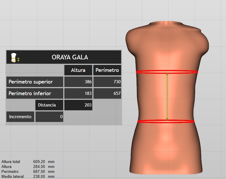
The following dialogue box will appear:
– The explanation for the dialogue box is as follows:
![]() indicates the tool that we are using.
indicates the tool that we are using.
Oraya Gala: is the name of the patient.
Top perimeter: we can see it in the form with a red line at the top, in the measurements tells us that it is 386 mm high and that its perimeter is 730 mm.
Bottom perimeter: we can see it in the form with a red line at the bottom, in the measurements tells us that it is 183 mm in height and that its perimeter is 657 mm.
Distance: is the length between the two perimeters, represented in the shape by two red lines (in the example above 203 mm).
Incremento: is the increase or decrease that we want to give between the two perimeters (red lines).
NOTE: if the dialogue box in the current view bothers us, we can change it. To do this, click in the box where the patient’s name appears, and without clicking, drag the dialogue box and position it in the desired zone.
The selection of the increase or decrease can be made in two ways:
-In the box corresponding to increment, we can write the desired value.
-With the mouse wheel (and with the box enabled), we can also increase or decrease the value. Once selected the value press enter, we will see in the form how the perimeters move to the selected distance.
Once selected the value press enter, we will see in the form how the perimeters move to the selected distance.
If we click on one of the two red perimeters (when activated it will happen to be yellow) we will be able to raise it or lower it at our criterion, dragging the red line.
After the change is made, you must validate it or not by clicking on ![]()
Finally, you must save the change by clicking on
Flexion
Go to Position
Click on Flex ![]()
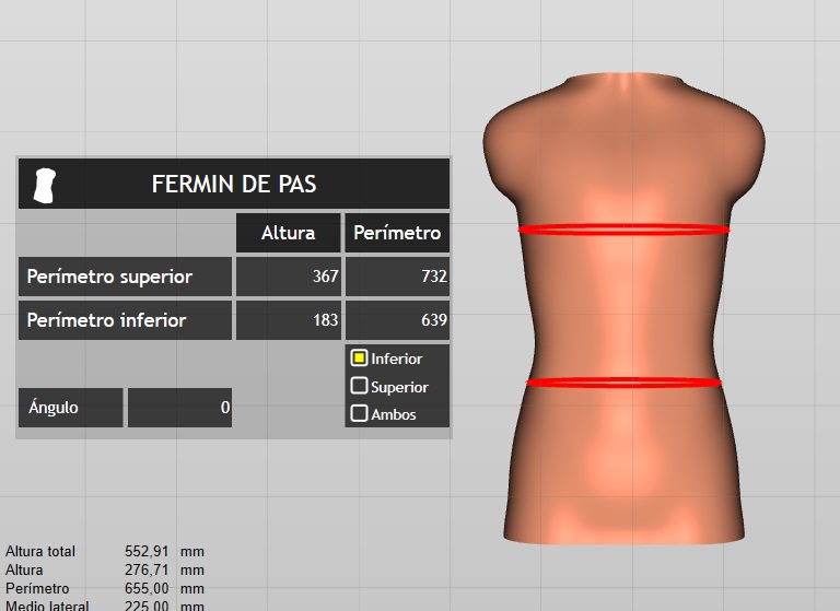
The following dialogue box will appear:
– The explanation for the dialogue box is as follows:
![]() indicates the tool that we are using.
indicates the tool that we are using.
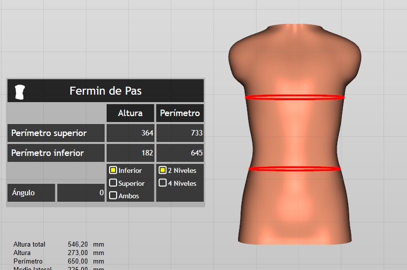
Fermín de Pas: is the name of the patient.
Top perimeter: we can see it in the form with a red line at the top, in the measurements tells us that it is 367 mm high and that its perimeter is 732 mm.
Bottom perimeter: we can see it in the form with a red line at the bottom, in the measurements tells us that it is 183 mm in height and that its perimeter is 639 mm.
Lower-Top-Both: in the box, we choose which part of the form is flexed.
Angulo: measures the flexion angle.
NOTE: when doing the flex, one of the red perimeters will turn to yellow. The red indicates until part of the shape stays fixed without flexing. The yellow perimeter is the one that flexes.
The increase of the flexion is realised first marking the zone to flex (superior, inferior, both). Then, enter a value in the white box, we can also use the mouse wheel while pressing the control key to enter a value.
+ ![]()
After the change is made, you must validate it or not by clicking on ![]()
Finally, you must save the change by clicking on
NOTE: after the flexion is done, we can change it or retouch it, pressing the red perimeter to which we have made the flexion (not the fixed) by clicking on it and dragging it to the point that we want.
Torsion
Go to Position
Click on Torsion ![]()
The following dialogue box will appear:
– The explanation for the dialogue box is as follows:
![]() indicates the tool that we are using.
indicates the tool that we are using.
Fermín de Pas: is the name of the patient.
Top perimeter: we can see it in the form with a red line at the top, in the measurements tells us that it is 364 mm high and that its perimeter is 733 mm.
Bottom perimeter: we can see it in the form with a red line at the bottom, in the measurements tells us that it is 182 mm in height and that its perimeter is 645 mm.
Lower-Top-Both: in the box, we choose which part of the form we want to perform the torsion.
2 levels – 4 levels: By default, it will be marked 2 levels. But we can mark the 4 levels.
Angulo: measures the flexion angle.
NOTE: if the dialogue box in the current view bothers us, we can change it. To do this, click in the box where the patient’s name appears, and without clicking, drag the dialogue box and position it in the desired zone.
The increase of the torsion is realised first marking the zone to flex (superior, inferior, both). Then, enter a value in the white box, we can also use the mouse wheel while pressing the control key to enter a value. +![]()
After the change is made, you must validate it or not by clicking on ![]()
Finally, you must save the change by clicking on
NOTA: after the torsion is done, we can change it or retouch it, pressing the red perimeter to which we have made the flexion (not the fixed) by clicking on it and dragging it to the point that we want.
Radios
Go to Position
Click on Radios ![]()
The following dialogue box will appear:
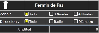
 indicates the tool that we are using.
Fermín de Pas: is the name of the patient.
Zone: indicates the zone of influence when we make the changes. It can be everything (when we will change the whole form) 3 levels (when changes are only made in the centre line) and four levels (when changes will be made in the segment between the two centre lines).
Addres: will indicate the address in which we made the changes. It can be everything (all the perimeter of the form), radius (when done in the direction that marks the yellow arrow, from the central axis of the form) and diameter (when done in the direction that marks the line of the arrow Yellow, throughout the diameter of its axis).
Amplitude: the dimension in mm of the changes that we are making.
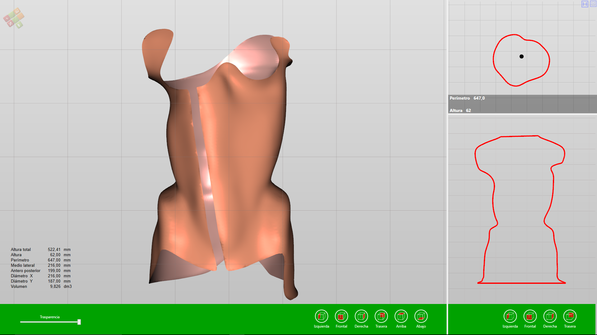
NOTE: This tool is very important to master and understand the cross-sectional view.
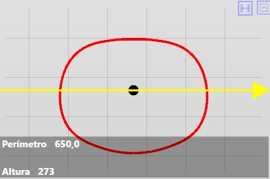
If we drag with the cursor the yellow line of the form we will vary the height of the transversal view:
In the tool radios, we can see the changes we make in the cross section with a yellow line.
When using zone three levels or four levels and in addres we use radios or diameter we can easily change the direction of the modification, rotating with the cursor the model.
Free forms multipoint
Go to Tools 
Click on Free forms multipoint ![]()
First, we must mark the outline:
Once the contour has been made, we can activate it for a possible relocation:
We mark the “crest” or highest point or if we sink the shape the lowest point:
Once the crest is made, we can specify some variation, we can even eliminate or add some point:
We give or remove volume with the mouse wheel:
After the change is made, you must validate it or not by clicking on ![]()
Finally, you must save the change by clicking on
To make a mirror copy of a form already done, we must follow the following steps:
Go to the historical by pressing the H (upper right corner).
A dialogue box will appear with the history of all movements made in the form we are working.
Right-click on the date and time of the free form that we want to copy and we can see the following options:
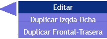
Edit: it will allow us to edit the form already made and make some changes. For example, if we “click” on one of the points of the contour and keep the cursor pressed we can drag it, varying its position, therefore also will vary the shape of the contour.
If we double click on any of the yellow contour points, it will change to orange, and holding down the cursor we will be able to move the entire contour and reposition it wherever we may.
If we click on an extreme point of the crest, we will erase it.
Duplicate Left-Right: selecting this option automatically open the same contour, with the same crest on the side opposite to the one made. Visually you will not see it until you go back to the historical and click on the new form. This new form will be totally the same but made the mirror. It will not have any variation or intensity at the level of growth or sinking, to realize this change you must use the mouse wheel in conjunction with the control key.
Duplicate Frontal-Rear: like the previous one, duplicate the forms that are in the front or back, copying it in mirror on the opposite side.
After the change is made, you must validate it or not by clicking on 
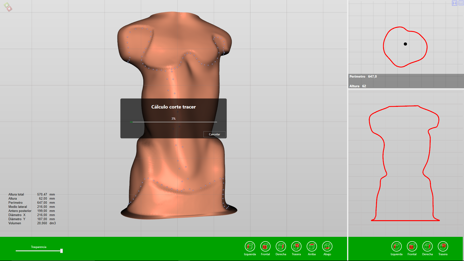
CAM cut
With this tool, you can make a cut to the 3d shape after finishing its design and before sending it to its reproduction by milling, in order not to reproduce any part of the unnecessary 3d shape.
The logic with which the software acts when we have marked the cut zone, is to disappear the smallest part and keep the largest.
NOTE: In the .ort file we will always see the full 3D shape, with the perimeter “purple” if we have activated and saved it. Even in the historical, it will appear as one more tool. It will only take effect when we export it to STL.
Go to Position
Click on Cam Cut ![]()
Draw an imaginary line on the 3D shape on the point that we want to make the cut. Press and hold the left mouse button.
A purple colour perimeter will appear indicating exactly the area of the cut.
This purple colour perimeter we can reposition it up or down, simply by clicking on it and holding down the left mouse button.
After the change is made, you must validate it or not by clicking on ![]()
Finally, you must save the change by clicking on
If we want to remove the CAM cut made only we must give the delete key (Supr) and we will get the following warning:
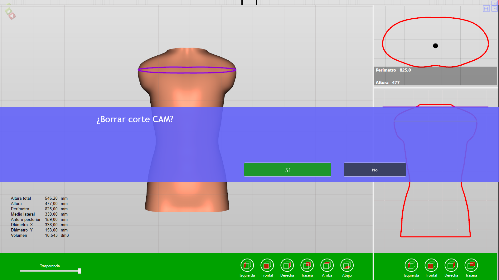
Click as appropriate.
Incorporating images
Before reading how to incorporate images into the corset module, please read this tutorial in the chapter on Installation Pi.Cas.So. , the sections:
- Arlequin.
- Link your smartphone or tablet to the Pi.Cas.So. software.
- Send photos from your smartphone.
- Receive photos.
In the chapter Databases of patients, prescribers and technicians, the section:
- Files assigned to a patient.
It is necessary to be clear that we must use the photos as a help, in no case we can establish the photos as a means of taking measures. However, to really be an aid we must count on taking the photos with some basic criteria.
Next, we insert a link as an example of the basic principles for taking photos.
http://www.ortoiberica.es/v_portal/inc/clicklink.asp?t=3&cod=223348&c=0&s=972589041
NOTA: the protocol of taking pictures that we indicate, only take it as the initial basis of work, take the photos based on your criteria and experience.
By clicking on the Image icon ![]() the following dialogue box will appear:
the following dialogue box will appear:
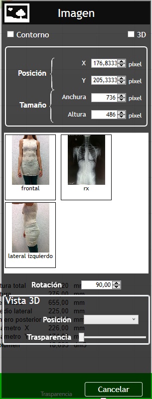
Perimeter/3D: we will choose the option if we want to insert the photo in the cross-sectional view or insert it in the central 3D model.
Position/size: in principle, is information that we should not change. The information refers to the size of the 3D shape.
Pictures: are the thumbnails of the photos that we have linked to our patient.
Rotation: allows us to rotate the image, clicking on the number will do it in 90º quadrants, the arrows will do it with more precision. In the example we must set it to 0, otherwise, it will rotate 90º when placing them.
Vista 3D/Position/Transparency: refers to the 3D view, in no case to transparency. In Position and clicking on the arrow, we can choose the position: front, left lateral, right lateral or posterior. Transparency, refers only to the photo, not to the 3D shape. The cursor of the 3D form in terms of transparency we will see below (in the green bar).
In addition to filling the dialogue box, we must choose the photo that we want to insert, with the right button we will cut the areas of the image that we are not interested.
At the bottom of the dialogue box, click Next: 
Insert a front image, we can also put aside image, that way you can see the two images rotating the 3D shape.
By choosing the option in the contour dialogue box, we can insert the image in the cross-section.
Always taking into account taking the image as assistance and measurements or scanning as the true dimensions to do the job. The software Pi.Cas.So. Allows us to install the image, to be able to vary its scale.
To do this the following combinations allow us to better accommodate the image in the form:
![]()
![]() (with the cursor over the photo) will allow us to scale the photo in length and width equally.
(with the cursor over the photo) will allow us to scale the photo in length and width equally.
![]()
![]() H
H ![]() (with the cursor over the photo) scaled in height only.
(with the cursor over the photo) scaled in height only.
![]()
![]() W
W ![]() (with the cursor over the photo) scaled in width only.
(with the cursor over the photo) scaled in width only.
Example of rectified corset with the X-Ray
Swinging
The Swinging tool allows you to balance the 3D shape with respect to its x or y axis, performing an exact symmetry without changing the volume. If it is not necessary to maintain the volume, use the tools Right reflection or Left reflection.
Go to Tools
Click on Swinging ![]()
When you select the tool you will see two cursors:
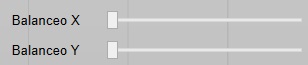
Balanceo X will balance the X axis and Balanceo Y will balance the Y axis. In the video example, the front view will be balanced by actuating X balance.
After the change is made, you must validate it or not by clicking on ![]()
Finally you must save the change by clicking on
Reflection
This tool, unlike the rolling, does not save the volume. Prior to its use, you should make sure that the 3d shape is well positioned on the axis.
In the palette of Pi.Cas.So. there are two possibilities: from left to right or from right to left.
Go to Tools
Clic on Right reflection or Left reflection ![]()
After the change is made, you must validate it or not by clicking on ![]()
Finally you must save the change by clicking on
Distilled
To see the functions and characteristics of this tool, please go in this tutorial to the Visor module to the Distilled section.
Its functions and explanations are the same.
The icon of this tool is represented in this module by 
Smoothing.
A very powerful tool with many possibilities, both to smooth shapes and surfaces as to eliminate irregularities.
Go to Tools
Clic on Smoothing ![]()
The following box will appear:
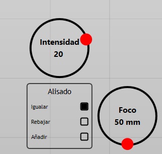
Two circumferences: Intensity and Focus.
Intensity: default will appear with 20. We can vary it by dragging the red dot clockwise with what will increase, if we move it to the opposite side, it will decrease. It will facilitate a greater or lesser action to equalize, reduce or add material.
Foco: default will appear with 50. We can vary it by dragging the red dot clockwise with what will increase, if we move it to the opposite side, it will decrease. It will facilitate a greater or lesser area of action following our interest.
Under the word Smoothing, three options appear: Equalize, Lower or Add. Its name already tells us the way the tool does the smoothing.
Equalize: equals the surface marked on the focus, the tool will raise the parts that are more deep down while lowering the parts that are higher. The tool is only activated when the cursor is in motion, if the cursor is still, it will not smooth.
Reduce: The tool will sink the highest parts to the lowest that are marked with the focus. It is a way to remove volumes or surfaces. It is very useful to remove folds of clothing, especially after a scan.
Add: the tool will equal the surface that is in focus looking the level of the highest part. It is a way of adding volumes or surfaces.
You can use different focus and intensities as well as different forms of smoothing before validating the resulting shape.
After the change is made, you must validate it or not by clicking on ![]()
Finally you must save the change by clicking on
Tracer
This tool will allow us to mark the line on the mold giving the final shape to the corset, to later make the cut. And in this way make the last step of the design of the corset, including the expansion windows if any.
To access, we must open the palette of Pi.Cas.So. Got to “Tools” and then to “Tracer” ![]() .
.
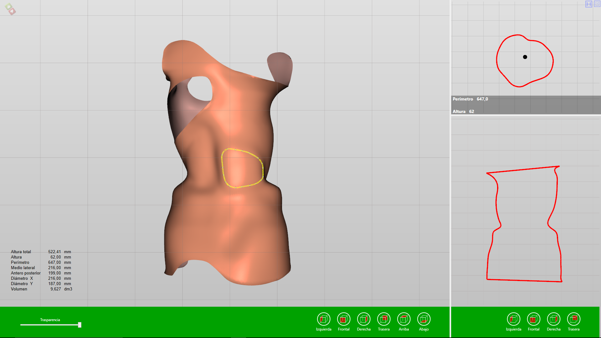
The following dialog box will appear:
Free tracer: we will choose this option when the cut that we are going to do does not have to be symmetrical, so that each point we mark will be independent of the others and will only affect the cut to the point made.
Symmetric Tracer: we will choose this option when the cut that we are going to make needs to be symmetrical, and each shape made with a sequence of points will be reproduced on the opposite side.
Chose the type of Tracer to use and press “Ok” ![]()
With the left button, we will mark one by one the points where we want to cut.
The first click will be marked with a darker spot than the rest. This point will be the first and the last, with this point we will close the layout and the design of the cut that we are going to make.

We will continue to mark the points, making the desired contour.
NOTE: In order that the final cut does not have imperfections, we advise not to space the points in the areas where there are sharp curves; while in the areas where the cut is more straight, we can space more the points.

When we close the form, clicking on the first point of the path, a yellow line will be formed that will indicate where the cut will be made.
We can modify this design by simply clicking on any of the points and dragging it to the desired area.

Subsequently, if we double click on any area of the part that we want to remove, the following dialog box will appear:
Taking into account the cut and the capacity of our pc, it will take more or less to eliminate the cropped area.
We can do the same operation if we want to do soma expansion window.
NOTE: the cut that we make, is an operation that we will be registered in the history, but with the traced marked, not with the definitive cut already made.
Export the cutout to the CAM, to be used in a cut with the router or robot.
Once we have completed the cut, we can send it to our router or robot to make an exact copy of the design made in the software.
For this, we will have to open the “historical” and in the corresponding boxes to the cuts or “tracer” made, leave them unmarked; in such a way that the shape will be designed but without any cut.
We will take it to “exits”, and later we will go to the icon “To exits”, where we will export the form in STL format. We will ask the application if we want to also export the “tracer” cuts, if we accept, two files will be created on the desktop:
- One of them will be the STL file, corresponding to the mold that we are going to mill.
- Another file will be an NCL format that will correspond to the “tracer” cuts that we have designed.
In the following video we can see the explained:
Export the cutout to the CAM, for use by a 3D printer