Visor Module
Is identified with the following icon:
Although its name indicates that it is a module to see forms in 3D quickly, even without having a patient selected, its importance is greater. Its use is imperative ALWAYS WHEN WE BEGIN A WORK WITH A SHAPE GIVEN FROM A SCAN, unless the form you used comes from the library. This action will be called “distilled”.
One of the most valuable features of Pi.Cas.So, is that it allows being used scanned files of any scanner that we find in the market. It is essential to use this viewer previously, this universality controls the different positions in the “space” and characteristics (like measurements) that have different manufacturers.
Introduce a form in the viewer:
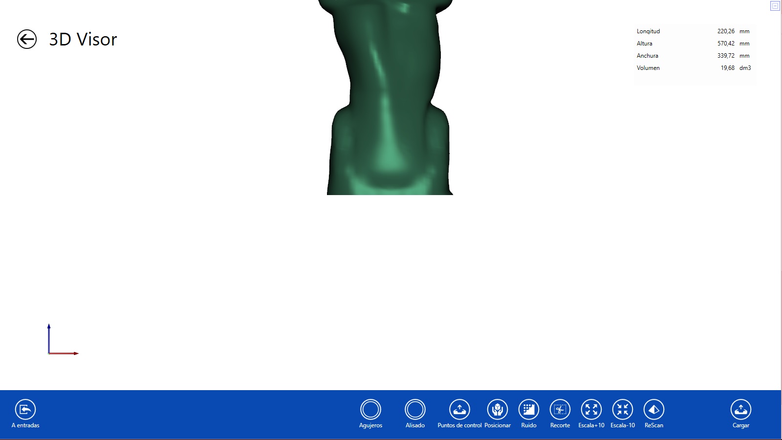
Click in the 3D Viewer module
Inside the module, we will click on Load 
It will take us by default to the desktop:
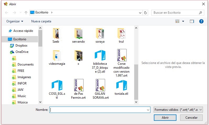
In allowed formats, we can see how allows us to load every ort, stl, and obj.
Click on the desired file.
Change to mm – dm – inch:
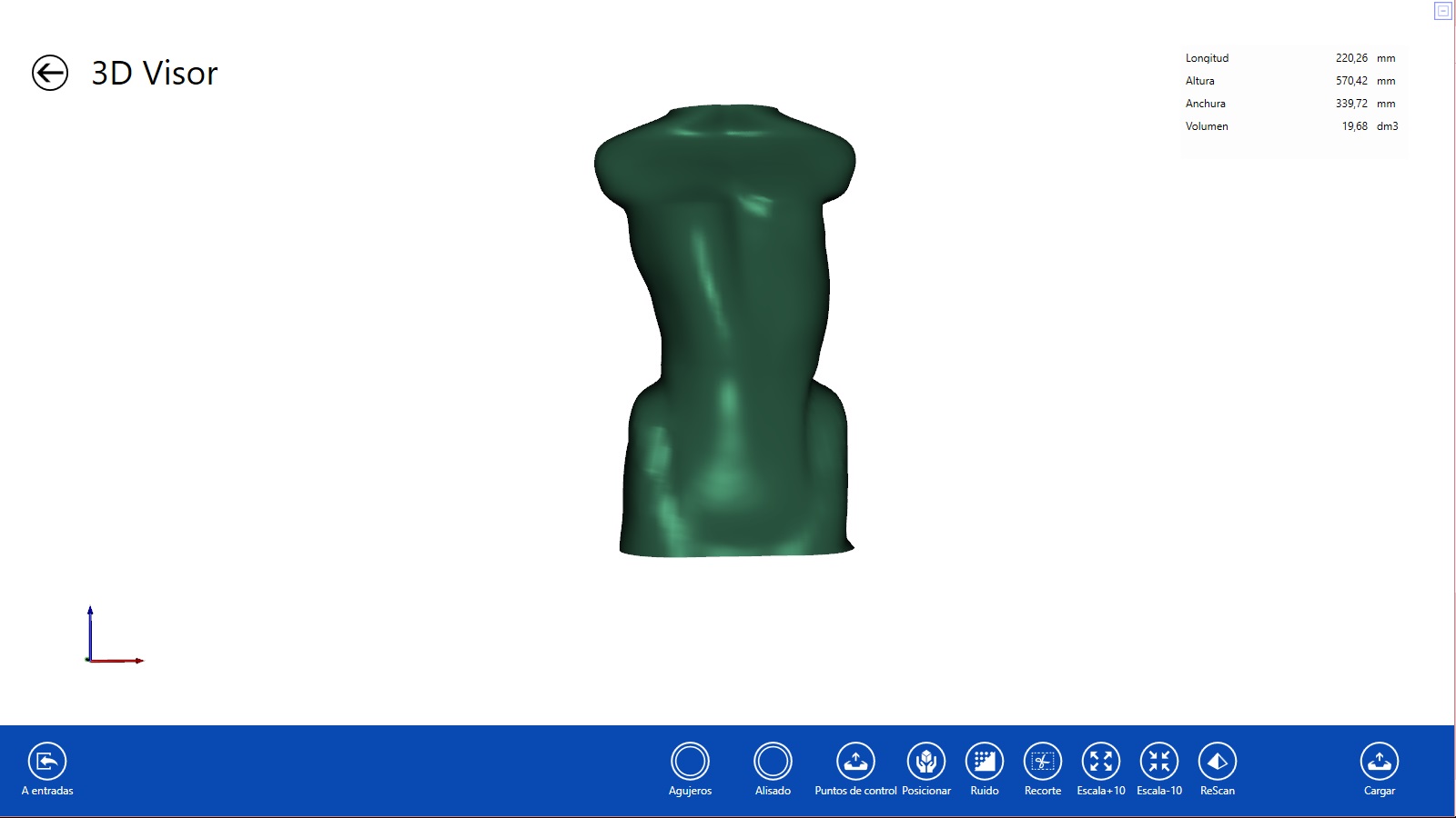
In the upper right corner we will see the following measurements in mm:
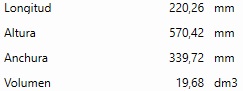
Lenght: expresses the depth of the shape.
Height: distance from the base to the top.
Width: measurement from side to side of the shape.
Volume: the volume of the shape.
Clicking on any point in this marker will change the measurements to cm and clicking another to inch.
Centre the shape:
Sometimes there are scanned forms that can not be seen in their entirety because they are not centred.
To view it quickly without having to position it (a step that we will see below) we can perform the following action:
Click and hold Shift ![]() + right mouse button
+ right mouse button ![]() Drag the shape to where you want.
Drag the shape to where you want.
The cursor ![]() will become
will become ![]()
Form in box:
To enter the boxed form, we must click on the “CAD axes” located at the bottom left.

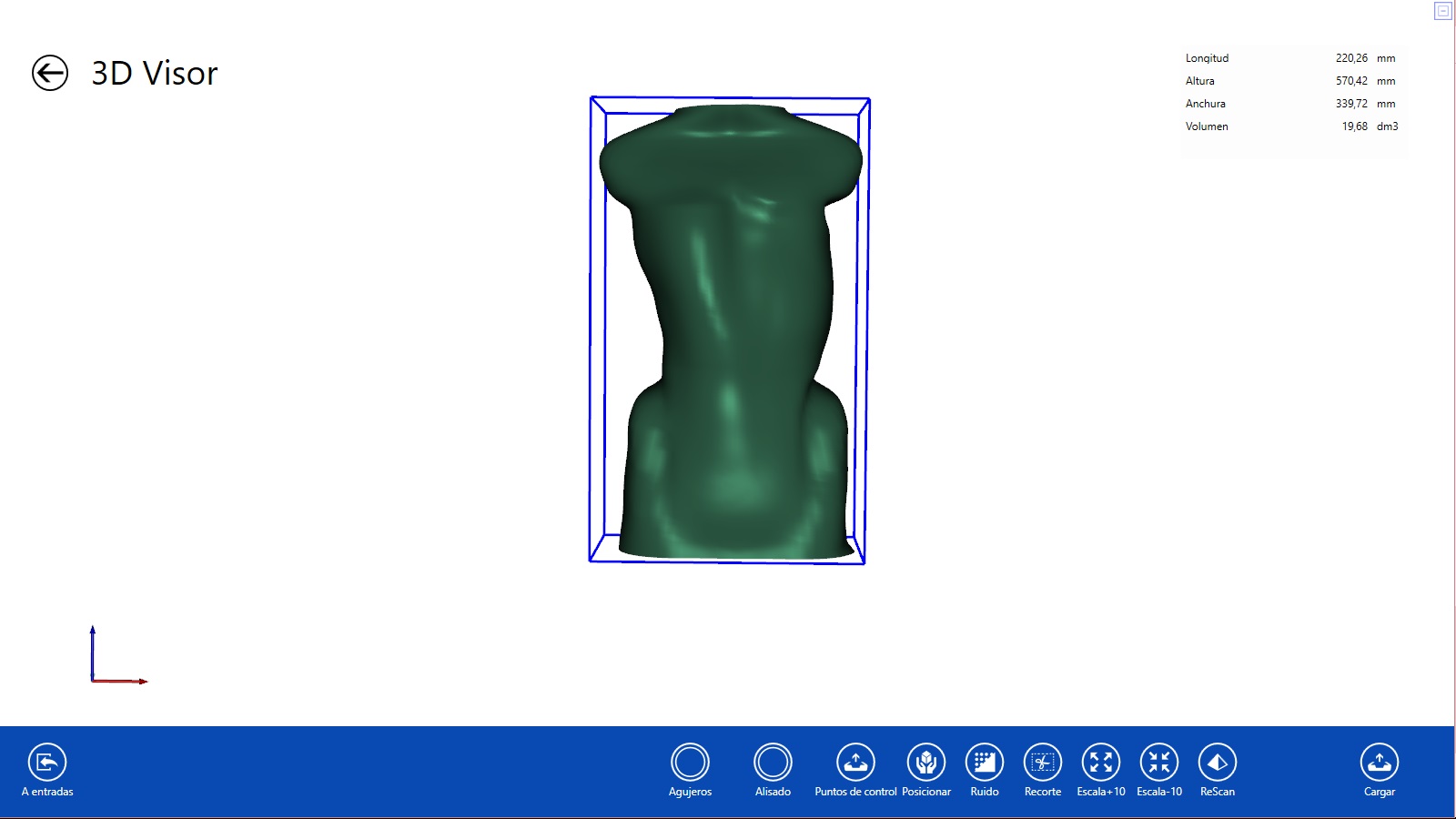
The view of the “form in box” is interesting to determine if the shape has noise.
Noise in the CAD / CAM: we call the forms that have external impurities and they are scanned, so we are part of it form (see below, how to remove noise).
It also gives us a better understanding of the reference measurements explained above, which appears in the upper right.
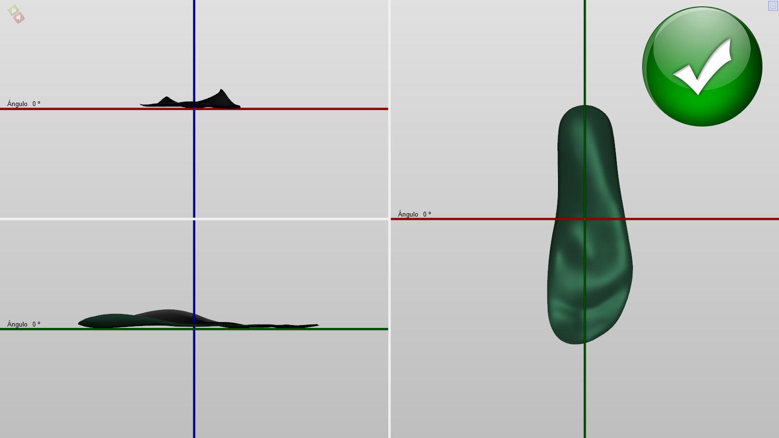
Position:
We call positioning to make a perfect placement in space in relation to the three axes (x, y, z) of the form, so we can apply correctly the modification tools or also send the modified form to the CAM (be it a carver, milling machine, robot or 3D printer) so that it can be positioned on the axes of the machine.
Each newly scanned form will have an arbitrary position according to the manufacturer of the scanner and according to the direction that we have made it, so it is very important to position it in space properly.
Template:
Dynamic Orthotics:
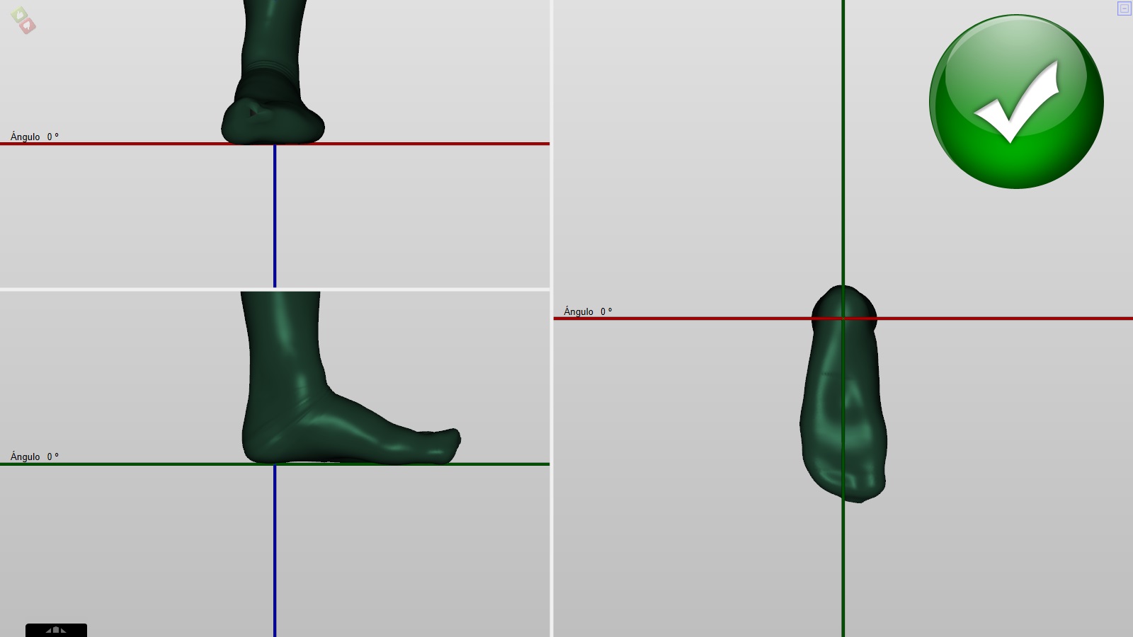
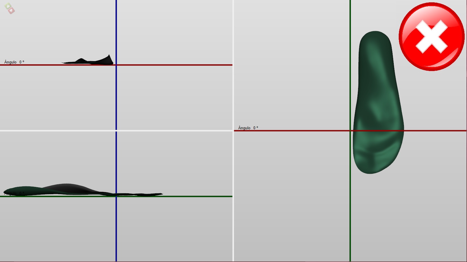
In the correct placement, we see how the z-axis (blue) is centred on the heel and the shape not only touches the x-axis (green), its inside.
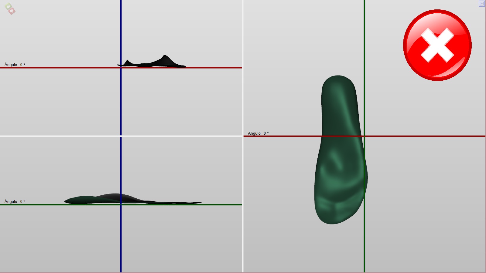
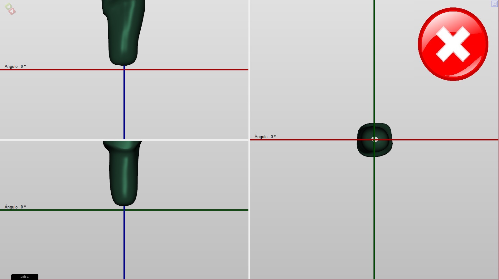
In the first example, we see is not correct, the model is one millimetre above the x-axis (green).
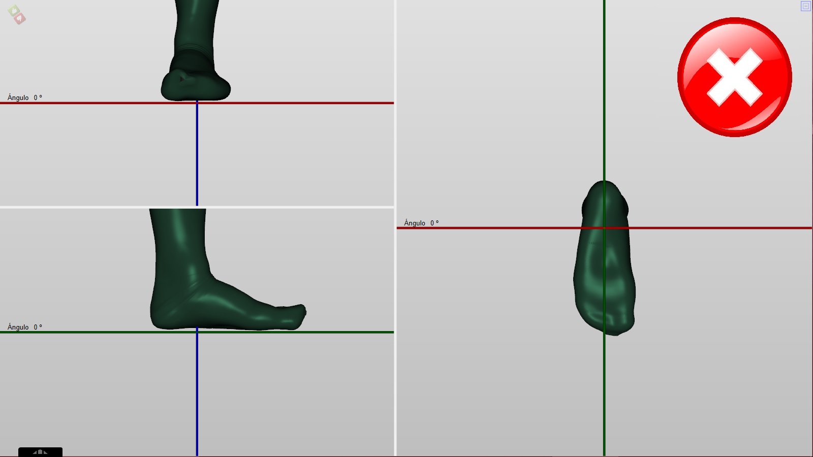
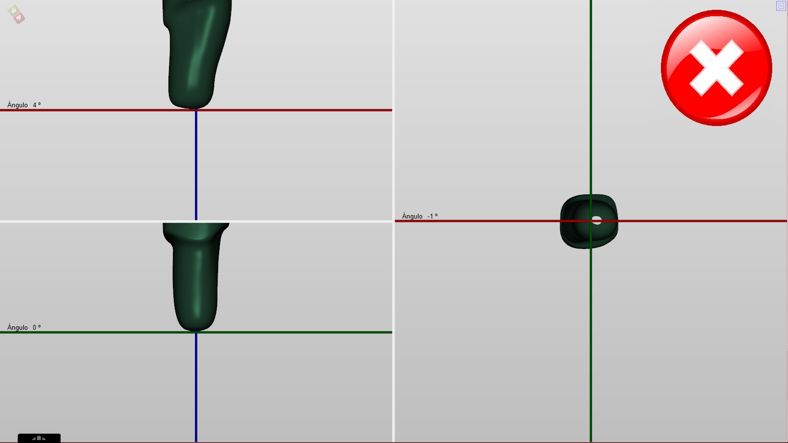
In the second example, we see is not correct, the foot in relation to the x-axis (green) is flanked to the right.
Prótesis AK & BK:
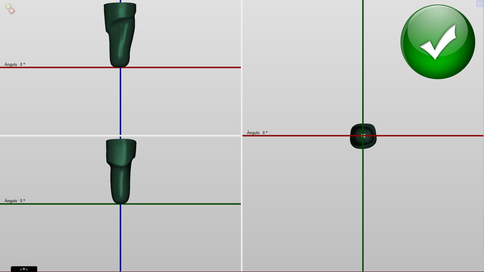
In the correct placement, we see how the z-axis (blue) is centred on the heel and the shape not only touches the x-axis (green), its inside.
In the first example, we see is not correct, the model is several millimetres above the x-axis (green).
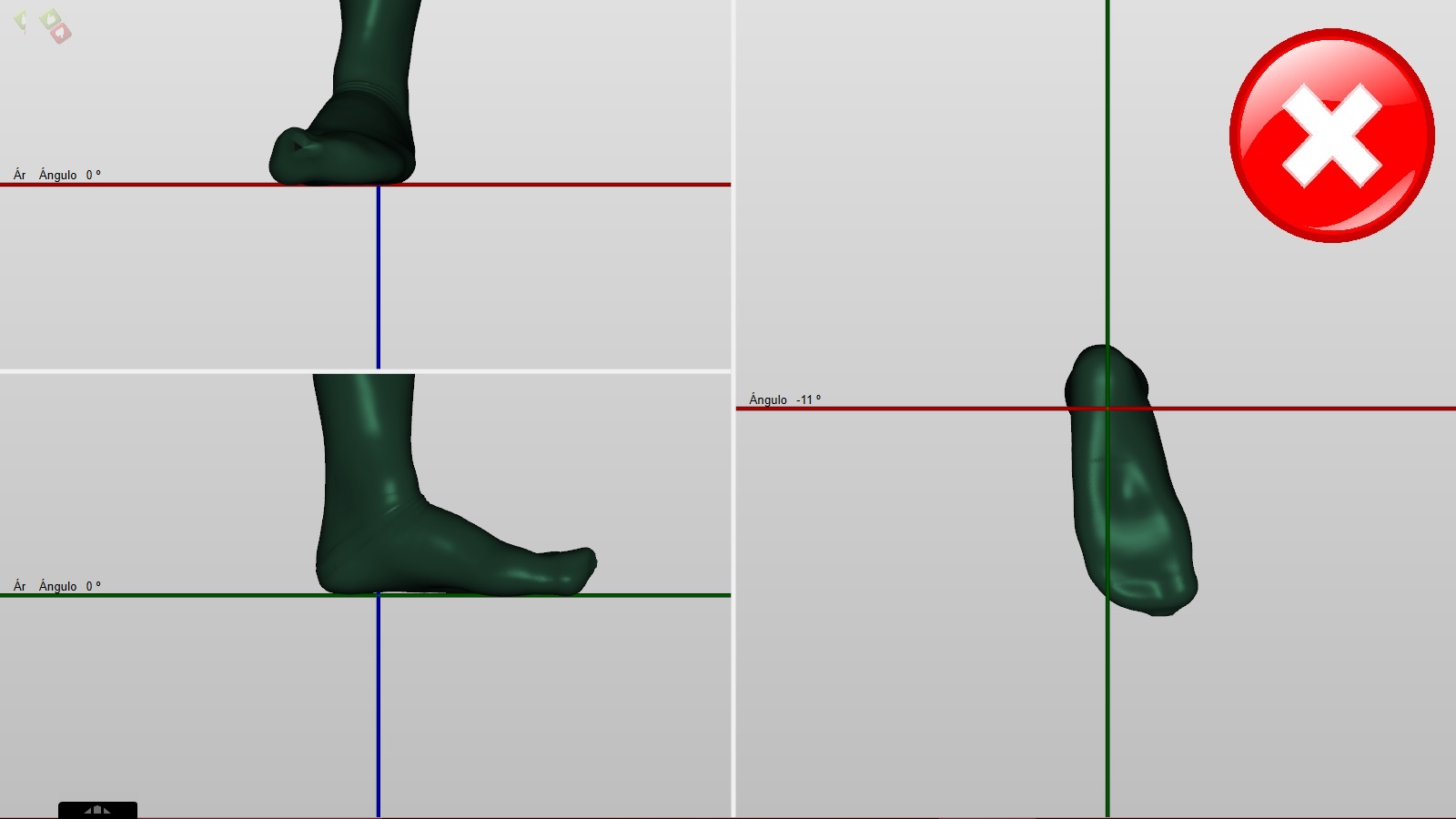
In the second example, we see is not correct, the z-axis (blue) it is not centered on the vertical of the shape.
Distilled
One of the most valued features of Pi.Cas.So., the same software allows working in 3D shapes with different geometries, such as a template (a plane), a prosthesis and a corset (circular shape) and a kafo or seat (two plans), becoming an integral software for the orthopaedic profession.
The action of distilling is to remove the impurities to the file, at the same time it organises its internal structure (mesh) to be able to make the necessary modifications. This action is mandatory in all newly scanned forms (it will be done in the viewer module as a previous step to enter it in the corresponding module). In the forms of the library, this step is not necessary (already done previously).
The icon appears on the bottom bar after selecting a 3D shape 
When activated, it will appear:
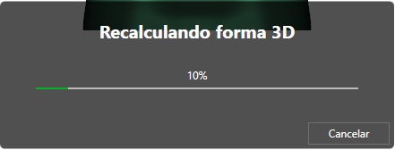
NOTE: The duration of this process depends on the capacity of each team.
After making the distillate we must take the file to inputs  and then assign it to a patient (see the tutorial: patient databases).
Noise:
In the use of CAD and 3D shapes, we call “noise” to the scanned forms that have particles or structures in the orbit of the main 3D shape. These particles in many cases are reflections, brightness or changes of light, the scanner gives form and creates a mesh that we then solidify. It occurs both in laser scanners, structured light or sensors.
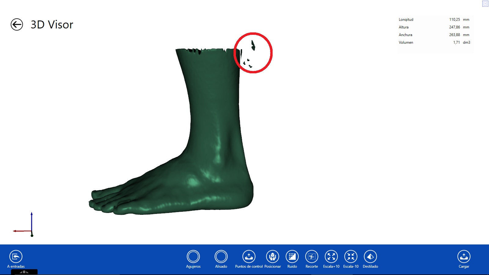
It is important to clean the form because the software interprets that it is part of the 3D form.
NOTE: Another way to detect these particles is through the “form in box” view. (See in this chapter Form in box).
In the lower blue bar, when the 3D shape is already in the viewer, different tools will appear.
Noise icon ![]()
Clicking on the icon, the cursor is changed to a “pen” ![]() and the following information is displayed.
and the following information is displayed.
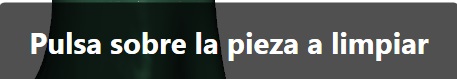
Move the cursor (pen) to the main shape and click.
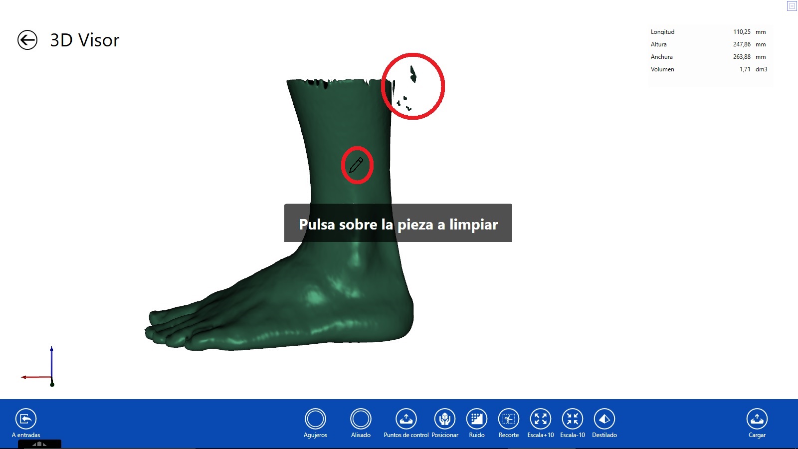
After this operation, the software will take a few seconds and clean the form.
Changes are not saved in the “Viewer“. We must continue making modifications or take the form “to entries” for the introduction in the corresponding module.
Cut:
At the bottom, we can see inside the blue bar the icon Recorte (cut)

Clicking on the Recorte option with the left button will be able to select the area that we want to eliminate. The software will delete the area within the marked box. The time it takes to disappear the cut area will depend on the capacity of the computer.
We will repeat the process to recut.
Undo the crop:
We can recover the 3D shape we had before the cut. To do this we have to press the keys together:
![]()

So many times we repeat the action, we will recover the cuts made.