AK & BK Prothesis Module
It is identified with the following icon:

From this module, we can make lower limb prostheses (tibial and femoral). The tibialis should always be done from scanning, the femoral ones, although they can also be done from a scan, it is recognised that with the use of a personalised library the results are very good.
Remember that whenever the origin is a scan, we must take the image to the viewer to position the shape and “distilled” it, then we will go up to the corresponding module.
For the femoral it is enough to choose the model that we consider of the library and to upload it to the module.
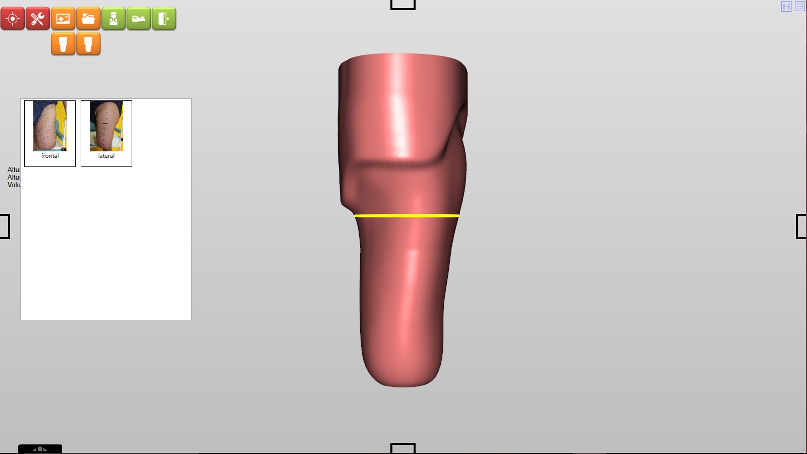
Mark level 0
Go to Position 
Click Mark level 0 ![]()
If we perform a femoral prosthesis we always recommend using the perineum as that level 0.
We must click on the yellow line, holding down the cursor and drag it to the desired point.
Validate changes ![]()
And save 
Height define
Go to Position
Click Height define 
We can do it in two ways: with the control key ![]() and the mouse wheel
and the mouse wheel  or by entering in the box the measured value of the patient’s wrist.
NOTE: the measurement should not be superficial, it must be the one referred to vertical.
Validate changes ![]()
And Save
Levels
Go to Position
Click Levels ![]()
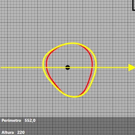
You can see a dialogue box and a cross-sectional view. The cross section corresponds to a perimeter view that matches the yellow mark in the 3D shape.
The dialogue box will be as follows:
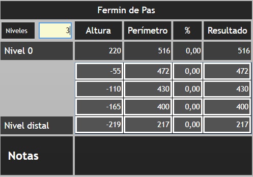
Patient’s name: in the example Fermin de Pas. Clicking on the name you can place the dialogue box on the site you consider.
Levels: You can put the number of levels you consider. There are two levels to which you must add the chosen levels, these two levels are level 0 (in the example the perineum), and the distal level (which will always be 1 mm in the form). When you put the number of levels you consider, the software will divide it into equal segments (in example four). If you do not want these levels you can go to the box with the value of each level and put the desired in the box corresponding to the height and click intro ![]()
Height: Indicates the height at which each level is located.
Perimeter: it will indicate the perimeter measurement in each one of the levels. To enter the measurements you have to enter the measurement in the corresponding box. After entering the measurement, press enter ![]()
%: We must put the percentage value of the reduction that the professional considers. Remember to set the negative value (-). Validate the value by pressing the enter key ![]()
Result: After the previous operation is performed, the resulting value will appear in this box.
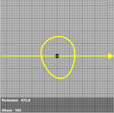
In the cross-section will appear:
Perimeter: indicates the perimeter measurement corresponding to the marked area.
Height: indicates the height at which the cross-sectional view is located.
We can zoom in the cross-sectional view by positioning the cursor in any area of the view, and using the mouse wheel.
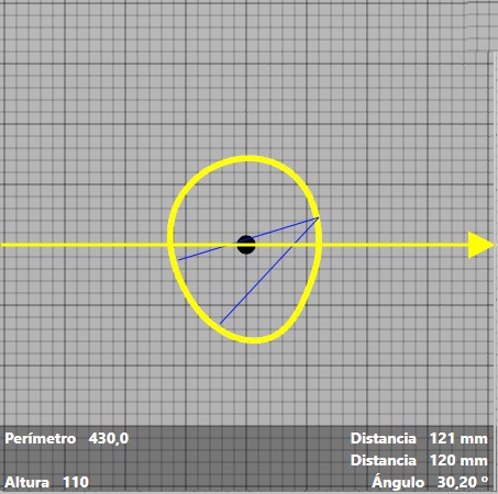
We can measure the distances and internal angles of the transverse view. We must click on the yellow line and hold the left mouse button until the distance you want to measure, a straight blue line will appear. You can make another line by double clicking, the software will mark the new blue line and the angle with reference to the previous line. Distances and angles will appear at the bottom of the cross-sectional view.
To change the cross-sectional view, click in the measurement dialogue box in the section corresponding to the height.
Remember that after making changes to the form you must validate the change ![]() and save it or not
and save it or not
To enlarge
Go to Position
Click on Stretch between levels ![]()
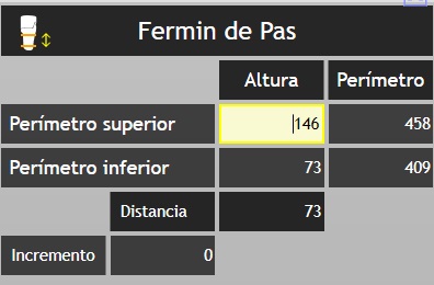
The dialogue box will be as follows:
![]() : indicates the tool we are using.
: indicates the tool we are using.
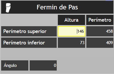
Fermin de Pas: is the name of the patient in the example. To move the dialogue box, click on the name and drag to the desired location. is the name of the patient in the example. To move the dialogue box, click and hold on the name and drag to the desired location.
Upper perimeter: marked on the shape with a red line. The height box tells us how high it is. And in the next box, it indicates its perimeter measurement.
Lower perimeter: marked in shape with a yellow line. The height box tells us how high it is. And in the next box, it indicates its perimeter measurement.
Distance: indicates the distance between the upper and lower perimeter.
Increase: indicates the increase or decreases we have made between the two perimeters.
First, we must mark the correct position of each of the two perimeters. We will click on one of the two perimeters and hold the left mouse button dragging the perimeter up or down, leaving it in the place that we consider. Then we will do the same with the other perimeter.
Between the two perimeters will be the zone that we are going to extend or to cut.
To do this we can put a positive or negative value in the “increment” box, or by placing the cursor in the same box we can use the mouse wheel + the control key up (lengthening) or down (decreasing)  +
+
After making the changes remember to validate them or not ![]() and save them or not
and save them or not
Flex
Go to Position
Click on Flex ![]()
![]() : indicates the tool we are using.
: indicates the tool we are using.
Fermin de Pas: is the name of the patient in the example. To move the dialogue box, click on the name and drag to the desired location. is the name of the patient in the example. To move the dialogue box, click and hold on the name and drag to the desired location.
Upper perimeter: marked on the shape with a red line. The height box tells us how high it is. And in the next box, it indicates its perimeter measurement.
Lower perimeter: marked in shape with a yellow line. The height box tells us how high it is. And in the next box, it indicates its perimeter measurement.
Angle: indicates the degrees of flexion we are performing.
NOTE: the red perimeter in the flexion marks the area that is maintained without flexion, and the yellow perimeter marks the flexed area. Try to bring closer the yellow perimeter to red to make a real bend and not “twist” the shape. The distance between the two perimeters should be enough so that they do not touch, in order to avoid folds.
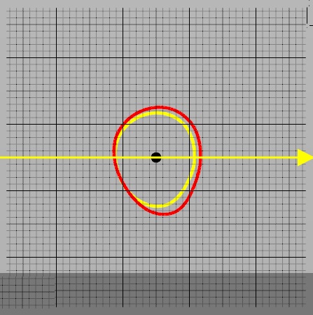
In the transverse view, you can see the two perimeters, red and yellow.
The yellow arrow indicates the direction of the bend. To change the direction of the flexion, “click” anywhere in the cross-view with the left mouse button![]() the cursor will change
the cursor will change ![]()
You can also change the direction of the bending by rotating the 3D shape with the left mouse button![]() the cursor will change
the cursor will change ![]()
To perform the flexion press the control key + the mouse wheel. You can also do it directly on the angle box, knowing the degrees of flexion you will perform.
After making the changes remember to validate them or not ![]() and save them or not
and save them or not
Radios
Go to Position
Click on Radios ![]()
![]() : indicates the tool we are using.
: indicates the tool we are using.
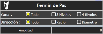
Fermin de Pas: is the name of the patient in the example. To move the dialogue box, click on the name and drag to the desired location. is the name of the patient in the example. To move the dialogue box, click and hold on the name and drag to the desired location.
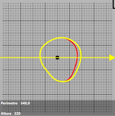
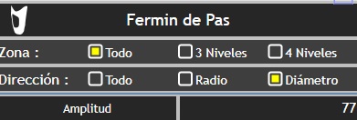
Zone: refers to the part of the 3D shape of influence. Can be All: complete form, 3 Levels: marked by the centre line (of the three that appear). 4 Levels: marked by the two central lines (of the four that appear).
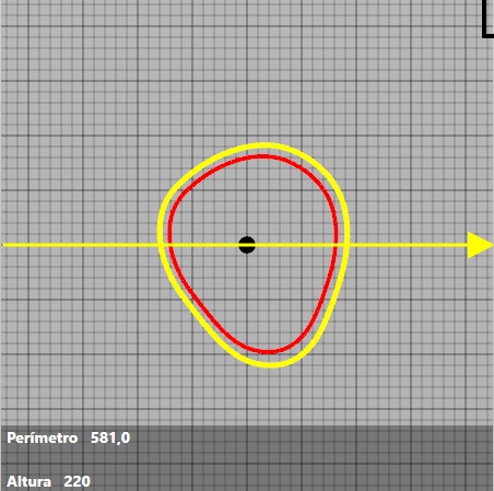
Direction: refers to the direction in which we are going to make the modification of the 3D form. It can be to All (when we want it to be in all directions), Radio (when we want to modify the radius), Diameter (when we want the modification to be made in the diameter). The modification will be made in the cross section represented by the yellow line.
Amplitude: shows the amount of decrease or increase that we are making in mm
The way to make the changes with the tool is done:
First by checking the appropriate options, in the corresponding boxes.
Press the control key and keep it pressed, use the mouse wheel forwards or backwards, as we want to increase or decrease the volume.
+
The cursor must be outside the cross-section.
We can appreciate the changes visualising the yellow line around the perimeter that are forming in the cross section. The yellow perimeter will indicate the modifications made, the red perimeter shows the old perimeter, before making the modifications.
For example:
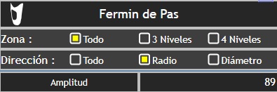
You can change the direction of the changes by changing the direction of the arrow. To do this, you have to move the cursor to the cross-section.
With the right mouse button, click and drag. The cursor changes and you will see: ![]()
You can make several modifications before you validate them.
Then you must validate them or not according to your criteria ![]() . And then save or not the changes
. And then save or not the changes
Smoothing
Go to Tools 
Click on Smoothing ![]()
It will appear on the 3D form a “focus” that when moving it will do a smoothing.
Two indicator cursors will also appear in the lower right.
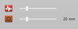
The upper icon indicates the intensity of the smoothing.
The bottom icon indicates the size of the tool. Its diameter is indicated in mm.
To change the intensities or diameter you must change the corresponding dial. Dragging with the mouse cursor.
Once the smoothing is done, we must validate the changes ![]() , and then save or not
, and then save or not
Mirror
Go to Tools
Click on Mirror ![]()
The tool allows you to change the side of the 3D shape, from right to left or vice versa.
Clicking on the tool icon, the change is made automatically.
Once the change is made, we must validate it ![]() , and then save it or not .
, and then save it or not .
Free forms multipoint
Go to Tools
Click on Free forms multipoint ![]()
First, we have to mark an outline of the 3D shape to modify.
We must click the left button of the mouse pointing to the zone. The first marked point will be bigger than the others, to close the form we must click on it again.
When you close the form, the selected points will be joined with a yellow line.
We can replace the points, modifying the selected contour, for this, you have to press a point and reposition it in the desired position.
Next, we will mark the crest, it is done in the same way, clicking the left mouse button marking the points. From the third point that we mark will join together forming a straight line between them.
We can also modify the position of the points of the ridge by right-clicking on one of them and repositioning it in the desired position.
Marked both the contour and the crest, hold down the control key and slide the mouse wheel forward (raising the crest), or back (lowering the crest), we will make the desired changes in the shape.
The increasing or decreasing of the crest will be indicated in the “reference measurements” in the “elevation” mark on the right side of the interface.
Once the change is made, we must validate it  , and then save it or not .
Picture
The incorporation of an image an image of the wrist is not a determining factor when it comes to precise measures, but it can be an aid in making decisions in mould rectification.
We can put two images (one front and one side image).
Click on Picture ![]()
Then choose the option of frontal or lateral, and we will leave all the images linked to the patient.
Clicking on the chosen photo will be placed on the 3D form.
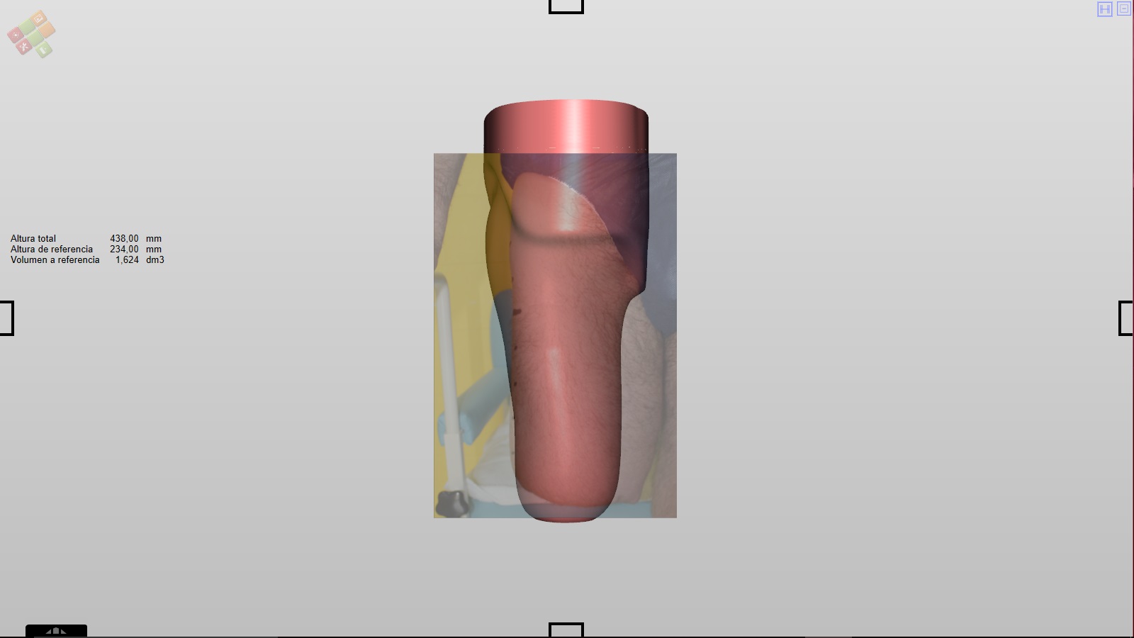
To place the photograph correctly you must click on the photograph and drag it.
The cursor will become ![]()
To increase or decrease the photo press the control key keeping it press, move the mouse wheel forwards or backwards
When the placement is correct we must validate and then save it or not
The same can be done by inserting a side photo.
We can keep the view of the two photos at once, being able to rotate the shape and see the two photos.
NOTE: viewing the photos are possible while we perform the rectification of the mould.
..
Sentinels