Pod Module
Is identified with the following icon:
We can make templates from a scan or from the library by scaling the shape to the 2D, as long as it has a real measurement, that is, at 1: 1 scale.
Introduce data.
After creating the patient (see how to create a patient in “databases: patients, prescribers and technicians”).
Double-click on the box that indicates your wallet.
If indeed (as an example) are a new customer, you have no linked file, its contents appear empty, and at the bottom, you will see a blue base that tells us we can add three possibilities:

Library: we can directly access the library where we have the most used forms (the library can always customise, see in this tutorial).
Model: The software will take us to entries, where we can choose a scan that we have previously passed through the viewer (see in this tutorial the module referring to the viewer).
Photo: also will take us to “inputs”, where we will have the photos uploaded or the ones received by Arlequin.
If we choose the Library option, we have to click on the “pie” (foot) –> “pantillas” (templates) and choose the folder you consider, the files are marked with a blue box.
If we select the files, including the photos, we can see a thumbnail on the right side that will help us perform the action.
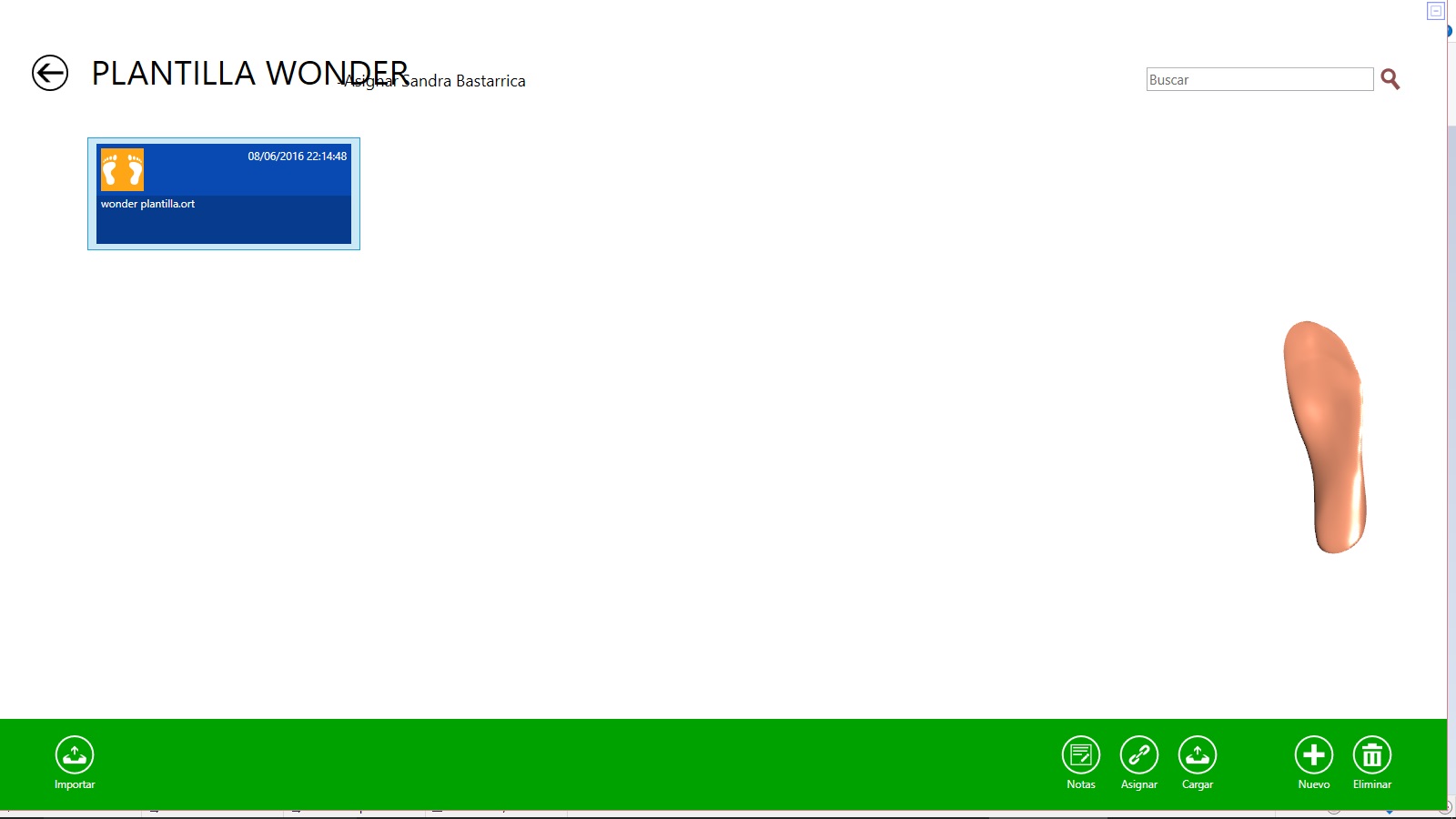
At the bottom we can see a green bar where we will have the following options:
Import: we can introduce new models in the software for the library.
Notes: it allows us to change the name of the staff of the library.
Assing: it will allow us to link to a certain patient.
Load: allows loading all the files from a folder on the library.
New: it allows to introduce the information of a new file including its name.
Delete: allows us to remove it from the library.
Work area and basic movements.
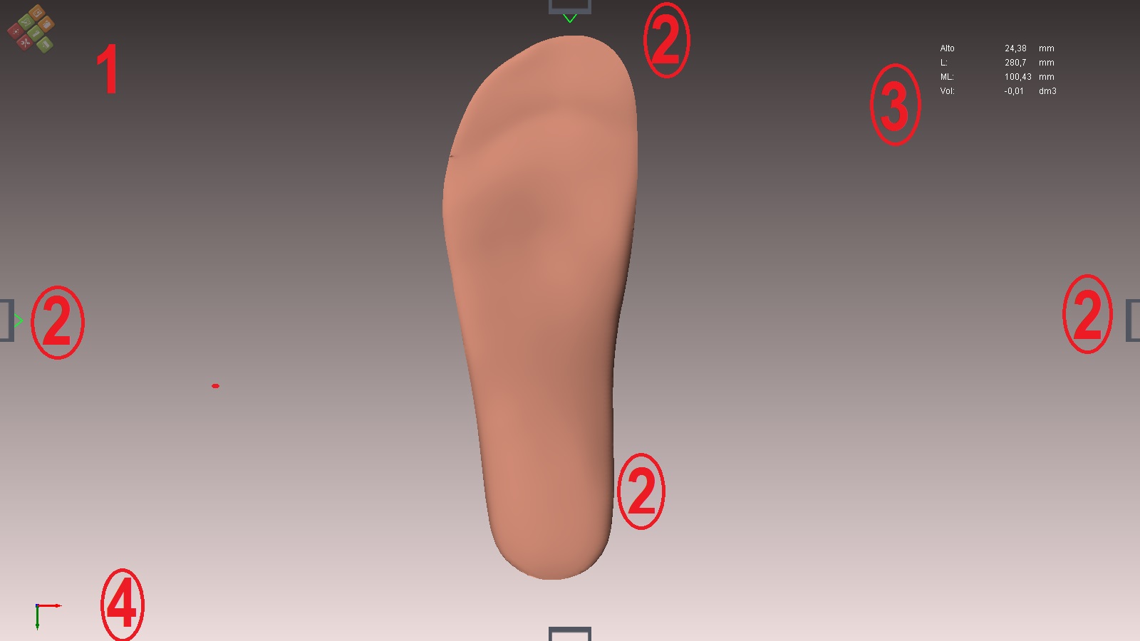
1.- Placing the cursor on the icon Pi.Cas.So. the available options will be opened.
2.- There are the quadrant positioners. Inserting the cursor in them will make movements of 45º. We can cancel them by clicking on their green vertex. To make them valid again click on the red vertex
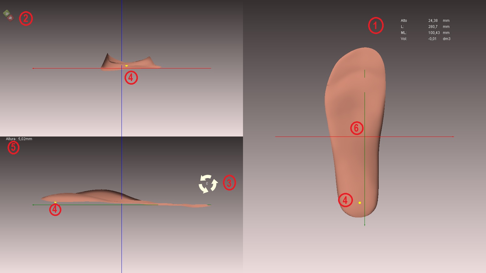
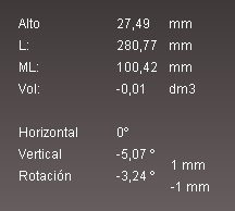
3 .- Measurement information of the form:
Height: mm height of the template, from its base to the top of it.
L: calculated by drawing a line in any cross the top, and another parallel to the bottom. The distance between the two lines.
ML: calculated by drawing a vertical line on the left side and a vertical line parallel to the above on the far right. The distance between the two lines.
Vol: it is the volume of the form (practically null or negative, it is a very fine and invaluable layer).
4: double clicking can see the x, y, z.
- Green: width: z.
- Blue: height: y.
- Red: length: x.
Movements of the form:
Zoom: mouse wheel. ![]()
Orbiting: right mouse button. ![]()
Traslation the form: press shift while holding down and dragging the right mouse button. ![]() +
+ ![]()
Rotation.
Go to Position ![]()
Clicking on Rotation ![]()
- Information measures form (see above in the work area and basic movements).
- Icons to accept or cancel changes.
- Cursor of rotation. To use it you must place it in any of the three views and the form will rotate with its axis being the line x (green), y (red) or z (blue). To rotate the shape you must hold down the control key
 by rotating the wheel of your mouse
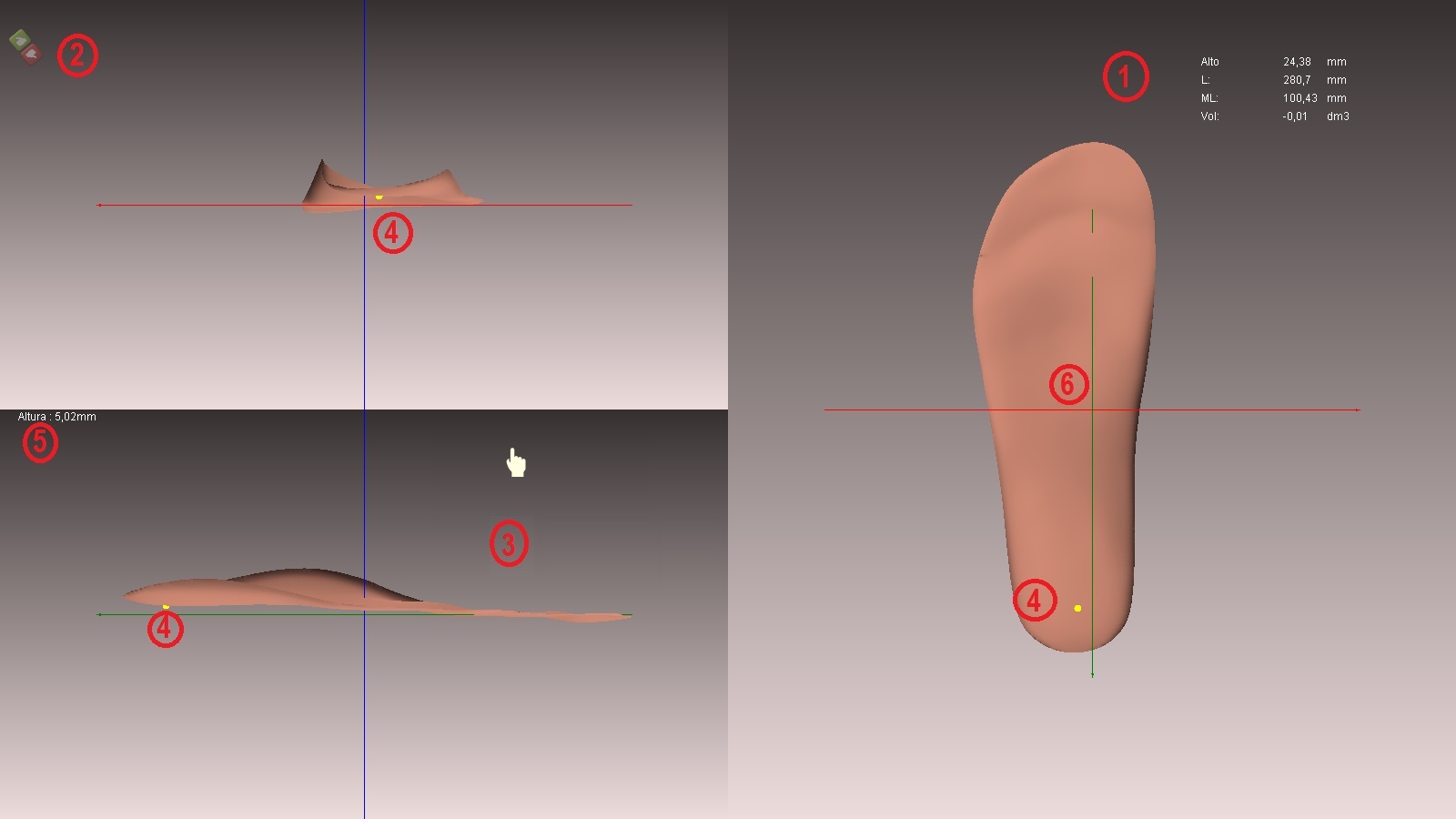
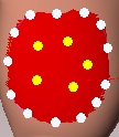
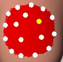
- The yellow point, pressed with the cursor in the desired area, determines the thickness of the template at that point (the distance from that point to the line x (green). The yellow point can be seen in any of the three views.
- The yellow point measurement.
- The correct position of the template. It must always be crossed by the three axes, and if possible it should be as centred as possible.
NOTE: Each type of product we design in CAD (template, corse, prosthetic AK, sandal, etc) has a specific placement, and in many cases different. This is because each element has a different CAM solution and we must position it in the appropriate scenario.
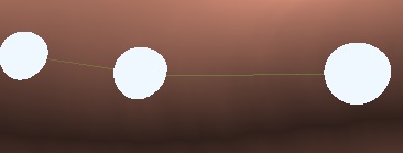
This tool is important in determining the “drop” the end of the template. See the following video:
Translation.
Go to Position ![]()
Clicking in Traslation ![]()
- Information measures form (see above in the work area and basic movements).
- Icons to accept or cancel changes.
- Cursor of rotation. To use it you must place it in any of the three views and the form will rotate with its axis being the line x (green), y (red) or z (blue). To rotate the shape you must hold down the control key by rotating the wheel of your mouse
- The yellow point, pressed with the cursor in the desired area, determines the thickness of the template at that point (the distance from that point to the line x (green). The yellow point can be seen in any of the three views.
- The yellow point measurement.
- The correct position of the template. It must always be crossed by the three axes, and if possible it should be as centred as possible.
IMPORTANT: Both in the “translation” view and in the “rotation” view, you can check the heights and thicknesses of any part or area of the template. To do this you have to do is drag the yellow point in the z-view (the big one or the image on the right), for the area you consider. You can see the height information on the left.
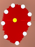
Torsion.
Go to Position ![]()
Click on Torsión ![]()
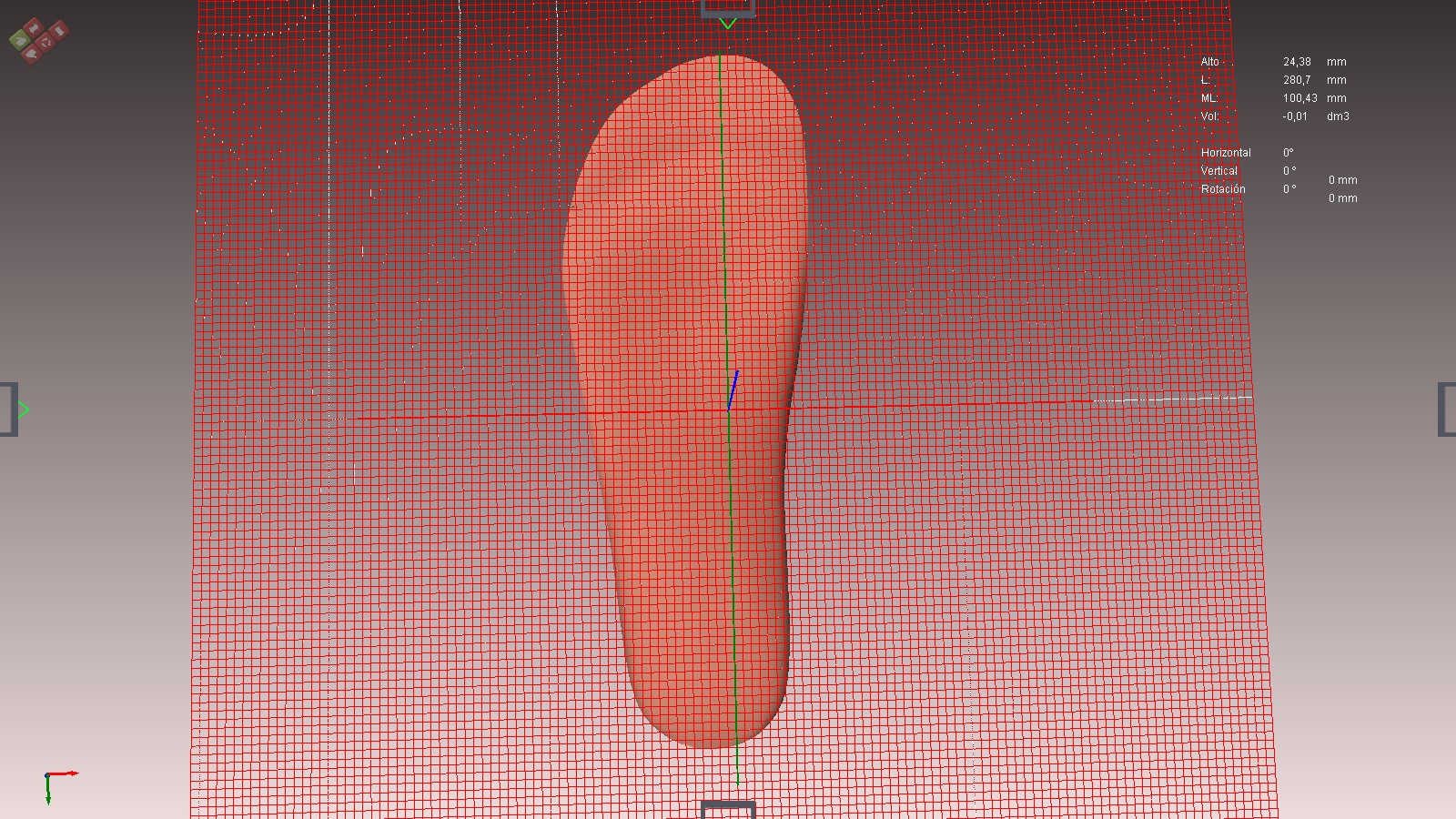
If the model plane is properly positioned it will appear with a grill at the bottom. We can orbit the best way to see it laterally.
Use positioners quadrant and orbit how to use other views (see above movements of the form).
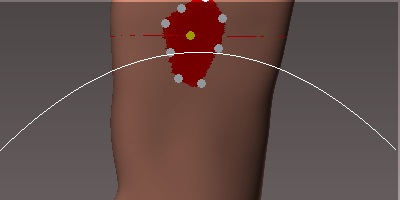
The objective is to place the plane of the grid that divides the shape into two parts, so that we make modifications in one of the parts while keeping the other fixed part unchanged.
To do this we must place the grid in the area that we consider using the keyboard.
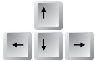
To perform more precise movements we must press the control key at the same time as the movement arrow.
+
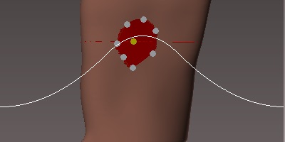
Placed the grill in the desired place we can choose between three possibilities to change the position in one of the two parts while the other part is fixed
NOTE: The software has no programmed limitations on the changes to be introduced, the anatomical knowledge and therefore the possible position both bone and muscle are of the user.
![]()
Clicking on the first possibility (double vertical arrow) the “grill plane” will move up or down if we use the mouse wheel.
Clicking on the second possibility (double horizontal arrow) the “grid plane” will move laterally using the mouse wheel.
Clicking in the third possibility (arrow rotation) a portion of the parts of the form will turn on itself, while the other will remain fixed. The movements are also made with the mouse wheel.
Following any change in the way you need to save or not the new form with the changes made.
After making changes, you can save or not.
![]()
In the upper right, below the “Measurement information of the form”, we will see the changes that we are producing both horizontally, vertically or in rotation.
Grill.
It is not a tool that modifies the form, but a tool to verify the heights of the surface of the template.
Go to Position 
Click on Grill ![]()
A grid will appear below the template.
As you rotate the mouse wheel![]() , you will see how the grid will go up vertically, following the vertical z-axis [blue], parallel to the x-axis [green] and y-axis [red].
, you will see how the grid will go up vertically, following the vertical z-axis [blue], parallel to the x-axis [green] and y-axis [red].
The template will appear indicating the height.
Cut.
Go to Position
Clicking on Cut ![]()
A scissor appears next to the cursor ![]()
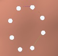
Click the left mouse button, marking the area where you want to make the cut.
The first point that will appear will be blue, it will serve as a reference, you will have to press and make points until closing the cut in the blue point.
To properly close the form, we must press the last point above the first blue, and it will become white.
If a white point is not in the proper position you can correct its position when the cut is closed.
Once closed the cut will be able to see a thin line between the points that will tell us where the cut will be made.
To change the position of any point, after closing the cut, we can click on any point and drag it to the desired position. When clicking on the point we will see how the drag icon will appear ![]()
When we want to make the cut, we must take the cursor out of the shape and click the left mouse button.
After making changes, you can save or not ![]()
NOTE: this type of cutting can only be done in cylindrical forms such as a foot, an ornament, etc; Never in flat shapes as a template.
Smoothing.
Go to Tools ![]()
Clicking on Smoothing ![]()
A yellow focus appears, will tell us where the smoothing is done
To resize the yellow focus, click on the control key and turn the mouse wheel. ![]() +
+ 
Choose the desired focus size, pass by moving the yellow focus by the shape. Smoothing will work by moving the cursor, (rubbing the focus by the shape), when it is still the smoothing will not work.
After making changes, you can save or not.

Espejo.
Go to Tools 
Clicking on Mirror ![]()
The shape, if it is on the right side, will become the left side.
After making changes, you can save or not.
Free forms.
With this tool, we can change the volume of a zone. We will mark the specific area and within it a point where we want to make the changes.
If we already have the model on the screen, we must perform the following steps:
Go to Tools
Click on Free form ![]()
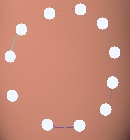
First, we must mark a specific area:
With the left mouse button, we will be marking points.
The first point is blue and the other white.
Mark the zone with points. To properly close the form, we must press the last point above the first blue, and it will become white.
If a white point is not in the proper position you can correct its position dragging it to the desired position
We will see how between two white points there is a thin line that actually delimits the free form.
Already marked the outline, we will mark the highest point.
Click the left mouse button.
The white points will mark the outline and the yellow dot the highest point.
Now we have to determine how we want to make the transition of height or depth, that is if we want to make it softer or more aggressive.
So that we can see the transition and therefore choose the one we want, we must press the control key.![]()
To vary the degree of transition we will move the wheel of the mouse by holding down the control key. ![]() +
+
Once the transition is selected, we stop pressing the control key and move the mouse wheel. Moving it forward the shape will come outwards, backwards we will sink the shape.![]()
In “reference measurements” in the upper right you can see the changes made.
After making changes, you can save or not.
Multipoint freeform.
This tool can make volume changes in a specific area. Marking the area and then, inside it, selecting several points.
If we already have the model on the screen, we must perform the following steps:
Go to Tools
Clicking on Free forms multipoint ![]()
First, we must mark a specific area:
With the left mouse button, we will be marking points.
The first point is blue and the other white.
Mark the zone with points. To properly close the form, we must press the last point above the first blue, and it will become white.
If a white point is not in the proper position you can correct its position dragging it to the desired position
We will see how between two white points there is a thin line that actually delimits the free form.
Already marked the outline, we will mark the highest point.
The white points will mark the outline and the yellow points the highest points.
As we explained in the free form we can vary the transitions (see free forms).
To make changes in one of the points, click on the chosen point and the others will change to white.
To re-select all the points click away from the form, all will be yellow again.
In “reference measurements” in the upper right you can see the changes made.
After making changes, you can save or not.
Incorporación de fotografías.
As long as the pictures are real size, it can be a good complement or resource for the design of the templates. The scanner step to step 2d, has the characteristic of working with pedigrapy in .jpg format and they are in real size, that is to say, in a scale of 1:1.
Definitely, before incorporating any picture in this section, make sure that the scale is correct.
Go to “Picture” ![]()
Two possibilities will open: “Load picture” ![]() and “Properties“
and “Properties“ ![]()
If we go to the first option “Load picture” we will open a window for us to search and select the image we want to import. The window will, therefore, be similar to:
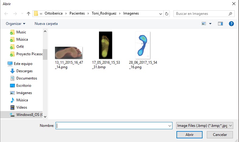
Where we will choose the image that we want to import and when selecting it or clicking on it, it will appear directly on the 3D model.
If we click on “Properties”, the following options window will appear:
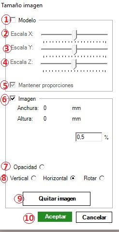
This option we will use when we already have an image inserted in the work tapestry, and we want to make some modification, some relocation on the model or remove it.
We will start by saying that we will call the 3D form “model“, and we will call the photograph that we have added “image“.
We will find the following options in the window:
1.-We will validate the Model box when we want to modify the 3D form.
6.-We will validate the Image box when we want to modify or position the photograph (picture).
2.-Scale X: If we move the cursor backwards or forward we will scale the image on the X axis, making it larger or smaller.
3.-Scale Y: If we move the cursor backwards or forward we will scale the image on the Y axis, making it larger or smaller.
4.-Scale Z: If we move the cursor backwards or forward we will scale the image on the Z axis (height), making it larger or smaller.
5.-The “Keep proportions” box, by default, is always validated, when we slide andy of the cursor X, Y or Z, the others will move proportionally. When we want to avoid this synchronization, we must invalidate this box, clicking on the validated box.
7.-Opacity: if we will validate the box, we can make the image more or less transparent. This option will allow us to simultaneously see both the 3D image, the photography or the photo. Changes in transparency and opacity can be made with the mouse wheel once the option has been validated.
8.-Vertical, Horizontal, Rotate: when we want to place the image superposing on the 3D shape, we can help with this option, choosing if the movements of the image we want to make are vertical, horizontal or we want to rotate the image. After the option is indicated, we will always use the mouse wheel.
When on the image we see the icon ![]() will allow us to drag the image for a perfect placement on the model.
will allow us to drag the image for a perfect placement on the model.
NOTE: remember the importance of working with images that have real sizes 1:1. This possibility will confirm us that the sizes and the zones in the 3D model are exact.
9.-Remove picture: after positioning the image correctly, we can use other tools with it embedded. Later, and when we do not need it, this option allows us to remove it.
10.-Ok and Cancel: obviously the words themselves clearly indicate the options. However, if we click Ok, will allow us to remove the dialogue box while maintaining the viewing of the image.